| |
TM 10-3930-671-24
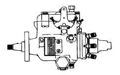
Idle Speed Adjustment
1.
Connect a tachometer to the engine.
2.
Adjust the idle speed setting by turning the idle
stop screw clockwise to increase speed or
counter-clockwide to decrease speed. Speed
should be adjusted until engine idles at 600 - 700
rpm.
3.
Remove the tachometer from the engine.
Accelerator Pedal and Linkage
NOTE
The
accelerator
throttle
linkage
assembly should not require periodic
adjustment. Check pedal linkage for
correct operation. (With engine not
running)
1.
Check
accelerator
pedal
travel.
Move
accelerator pedal to the fully-down position. The
pedal should stop without hitting the floorplate
(normally there should be clearance between the
pedal arm and the floorplate. This may vary in
some installations).
2.
Remove
the
floorplates
and
open
engine
compartment side door for access to throttle
linkage.
3.
Check for correct linkage adjustment. Move
accelerator pedal to the fully-down position.
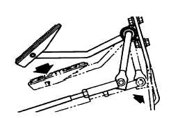
4.
Pedal travel should be stopped by the lower
pedal lever striking against the inside of frame
cowl, Figure 1.
Throttle Linkage Adjustment Procedure
NOTE
The
throttle
linkage
adjustment
procedure is the same for all models,
except Step 5, as noted below.
To adjust the throttle linkage, you must change the
length of the control rod between accelerator pedal lever
and the fuel control linkage as follows:
1.
Loosen the lock nut on clevis rod end at
accelerator pedal lever.
2.
Remove cotter pin and clevis pin from rod end.
Disconnect control rod from accelerator pedal
lever.
3.
Position accelerator lever assembly against
cowl. Pull the accelerator control rod until fuel
control lever is at wide-open throttle position.
4.
Adjust clevid rod end as necessary until it aligns
with hole in accelerator pedal lever (with lever
against cowl).
5.
After adjustment of throttle linkage, assemble
rod end to accelerator pedal lever. Install clevis
pin and cotter pin.
6.
Tighten lock nut on control rod against rod end.
7.
Check throttle linkage for correct adjustment.
F-108
|