| |
TM 10-3930-669-20
WARNING
Remove all jewelry such as rings, dog tags, bracelets, etc. If jewelry contacts battery
terminal, a direct short may result in instant heating of tools, damage to equipment, and
injury or death to personnel.
VOLTAGE TEST
(1)
Remove instrument panel (Para 7-
8).
(2)
Set multimeter select switch to
VOLTS DC.
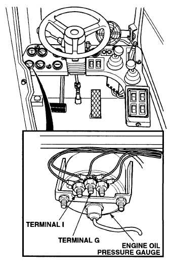
(3)
Connect positive (+) multimeter
lead to engine oil pressure gauge,
terminal I.
(4)
Connect negative (-) multimeter
lead to a known good ground.
(5)
Set MAIN POWER switch to ON
position (TM 10-3930-669-10).
(6)
Set
engine
switch
to
ignition
position (TM 10-3930-669-10).
(a)
If there are not 22 to 24 vdc
present, perform Steps (7) and
(8) below and repair gauge
wire
5
(see
schematic
Appendix F).
(b)
If there are 22 to 24 vdc
present, lead wire 5 is OK.
(7)
Set engine switch to off position.
(8)
Set MAIN POWER switch to OFF
position.
CONTINUITY TEST
(1)
Set multimeter select switch to
OHMS.
(2)
Check continuity between suspect
gauge, terminal G and a known
good ground.
(a)
If there is no continuity, repair
gauge
ground
wire
(see
schematic Appendix F).
(b)
If there is continuity, gauge
ground wire is OK.
2-63
|