| |
TM 10-3930-669-20
WARNING
Remove all jewelry such as rings, dog tags, bracelets, etc. If jewelry contacts battery
terminal, a direct short may result in instant heating of tools, damage to equipment, and
injury or death to personnel.
VOLTAGE TEST
(1)
Remove relay R4 (Para 7-33).
(2)
Set multimeter select switch to
VOLTS DC.
(3)
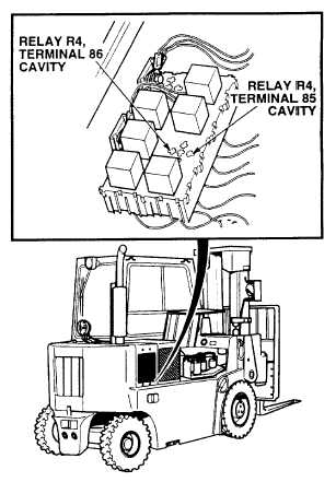
Connect positive (+) multimeter
lead to relay R4, terminal 86 cavity.
(4)
Connect negative (-) multimeter
lead to a known good ground.
(5)
Start engine (TM 10-3930-669-10).
(a)
If there are not 22 to 24 vdc
present,
perform
Step
(6)
below and repair wire 34 (see
schematic Appendix F).
(b)
If there are 22 to 24 vdc
present, wire 34 is OK.
(6)
Shut down engine.
CONTINUITY TEST
(1)
Set multimeter select switch to
OHMS.
(2)
Check continuity between relay R4,
terminal 85 cavity and a known
good ground.
(a)
If
there
is
no
continuity,
replace relay R4 ground wire
(See schematic Appendix F).
(b)
If there is continuity, relay R4
ground wire is OK.
2-53
|