| |
TM 10-3930-669-20
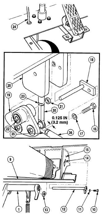
(3) Install two bushings (21) in cab
frame (20).
(4) Install two bearings (22) in pivot (19).
(5) Position fitting and linkage
assembly (36) in forklift, ensuring
linkage engages master cylinder.
(6) Install pivot (19) on cab frame (20) with
pin (18), screw (16), and washer (17).
(7) Turn rod end (35) to adjust linkage until
0.125 in. (3.2 mm) clearance is obtained
between fitting and linkage assembly
rod (36) and rod end (30).
(8) Insert rod (24) through floor and
assemble with nut (23) and rod end (30).
(9)
Install two bushings (14) on dash
frame (15).
(10) Install two bearing (13) in brake
pedal (1).
(11) Install brake pedal (1) on dash
frame (15) with pin (12), washer (11),
and screw (10).
11-23
|