| |
TM 10-3930-669-20
WARNING
Remove all jewelry such as rings, dog tags, bracelets, etc. If jewelry contacts battery
terminal, a direct short may result in instant heating of tools, damage to equipment, and
injury or death to personnel.
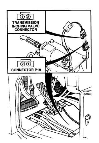
VOLTAGE TEST
(1)
Remove floor plate (Para 15-12).
(2)
Disconnect connector P19 from
transmission
inching
valve
connector.
(3)
Set multimeter select switch to
VOLTS DC.
(4)
Connect positive (+) multimeter
lead to connector P19, terminal 1.
(5)
Connect negative (-) multimeter
lead to a known good ground.
(6)
Set MAIN POWER switch to ON
position (TM 10-3930-669-10).
(7)
Set
engine
switch
to
ignition
position (TM 10-3930-669-10).
(a)
If there are not 22 to 24 vdc
present, perform Steps (8)
through (10) below and go to
Step 9 of this Fault.
(b)
If there are 22 to 24 vdc
present, Perform Steps (B)
and (9) below and go to Step
8 of this Fault.
(8)
Set engine switch to off position.
(9)
Set MAIN POWER switch to OFF
position.
(10) Install floor plate.
VOLTAGE TEST
(1)
Set multimeter select switch to
VOLTS DC.
(2)
Turn Main power switch to the ON
position (TM 10-3930-669-10).
(3)
Check for 22 to 24 vdc between
transmission
inching
valve
connector, terminals 1 and 2.
(a)
If there is not 22 to 24 vdc,
replace transmission inching
valve (Para 7-24).
(b)
If there is 22 to 24 vdc, fault
not corrected. Perform Steps
(4),
(5),
and
(6)
below.
Repeat procedure and notify
Supervisor.
(4)
Turn Main power switch to the OFF
position.
(5)
Connect
connector
P19
on
transmission
inching
valve
connector.
(6)
Install floor plate (Para 15-12).
2-401
|