| |
TM 10-3930-669-20
WARNING
Remove all jewelry such as rings, dog tags, bracelets, etc. If jewelry contacts battery terminal, a
direct short may result in instant heating of tools, damage to equipment, and injury or death to
personnel.
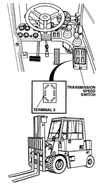
VOLTAGE TEST
(1) Remove
transmission
range
switch
(Para 7-19).
(2) Set multimeter select switch to VOLTS
DC.
(3) Connect positive (+) multimeter lead to
transmission range switch, terminal 2.
(4) Connect negative (-) multimeter lead to
a known good ground.
(5) Set MAIN POWER switch to ON
position (TM 10-3930-669-10).
(6) Set engine switch to ignition position
(TM 10-3930-669-10).
(a) If there are not 22 to 24 vdc
present, perform Steps (7) and (8)
below
and
repair
wire
10
to
transmission
speed
switch
(see
schematic Appendix F).
(b) If there are 22 to 24 vdc present,
perform Steps (7) and (B) below
and replace transmission speed
switch (Para 7-19).
(7) Set engine switch to off position.
(8) Set MAIN POWER switch to OFF
position.
VERIFY REPAIR
(1) Start engine (TM 10-3930-669-10).
(2) Set transmission range switch to HIGH
RANGE position (TM 10-3930-669-10).
(3) Observe and listen for speed and rpm
change.
(a) If transmission does not engage in
high range, fault not corrected.
Perform Steps (4) and (5) below
and repeat procedure and notify
Supervisor.
(b) If
transmission
operates,
fault
corrected.
(4) Park forklift.
(5) Shut down engine.
2-273
|