| |
TM 10-3930-669-20
WARNING
Remove all jewelry such as rings, dog
tags, bracelets, etc. If jewelry contacts
battery terminal, a direct short may result
in instant heating of tools, damage to
equipment, and injury or death to
personnel.
NOTE
Using wiring schematic to follow logic
flow.
CONTINUITY TEST
(1) Set multimeter select switch to OHMS.
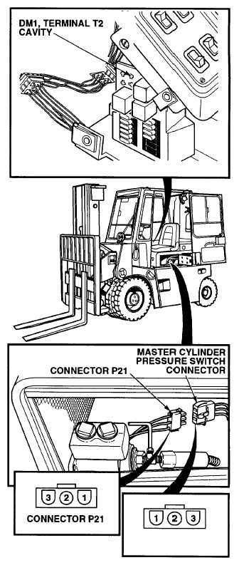
(2) Check continuity between master
cylinder pressure switch connector,
terminals 1 and 2.
(a) If there is no continuity, replace
master cylinder pressure switch
(Pare 7-17).
(b) If there is continuity, master cylinder
pressure switch is OK.
(3) Connect connector P21 on master
cylinder pressure switch connector.
(4) Close engine access panel (TM 10-
3930-669-10).
VOLTAGE TEST
(1) Remove diode module DM1 (Para 7-
33).
(2) Set multimeter select switch to VOLTS
DC.
(3) Connect positive (+) multimeter lead to
diode module DM1, terminal T2 cavity.
(4) Connect negative (-) multimeter lead to
a known good ground.
(5) Set MAIN POWER switch to ON
position (TM 10-3930-669-10).
(6) Set engine switch to ignition position
(TM 10-3930-669-10).
(a) If there are not 22 to 24 Vdc
present, perform Steps (7) and (8)
below and repair wire 10B (see
schematic Appendix F).
(b) If there are 22 to 24 Vdc present
replace diode module DM1.
(7) Set engine switch to off position.
(8) Set MAIN POWER switch to OFF
position.
(9) Install diode module DM1.
2-259
|