| |
TM 10-3930-669-20
WARNING
Remove all jewelry such as rings, dog tags, bracelets, etc. If jewelry contacts battery terminal, a
direct short may result in instant heating of tools, damage to equipment, and injury or death to
personnel.
VOLTAGE TEST
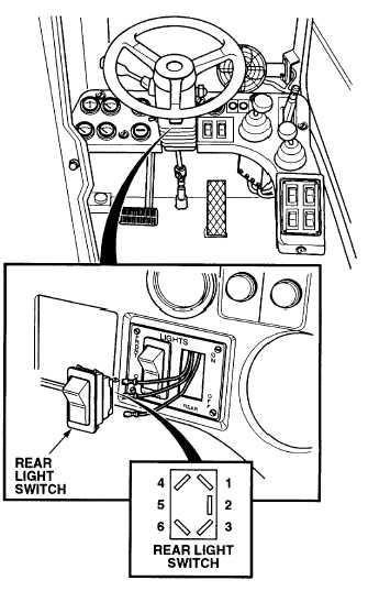
(1) Lift light switch from instrument panel (Para
7-16).
(2) Set multimeter select switch to VOLTS DC.
(3) Connect positive (+) multimeter lead to rear
light switch, terminal 2 (4) Connect negative
(-) multimeter lead to a known good ground.
(5) Set MAIN POWER switch to ON position
(TM 10-3930-669-10).
(6) Set engine switch to ignition position (TM
10-3930-669-10).
(7) Set rear light switch to ON position (TM 10-
3930-669-10).
(a) If there are not 22 to 24 vdc present,
perform Steps (8) through (10) below
and repair wire 24A (see schematic
Appendix F).
(b) If there are 22 to 24 vdc present,
perform Steps (8) through (10) below
and replace rear light switch (Para 7-16).
(8) Set engine switch to off position.
(9) Set MAIN POWER switch to OFF position.
(10) Set rear light switch to OFF position.
2-173
|