| |
TM 10-3930-669-20
(2)
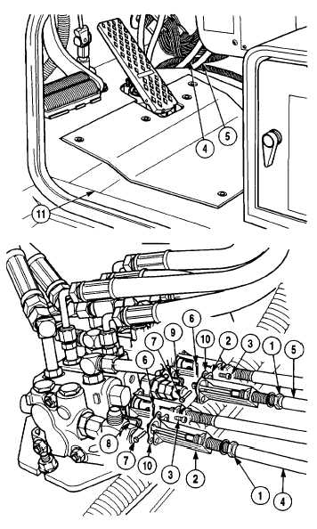
Position cables (4 and 5) through access hole in
cab frame (11).
NOTE
·
Connect cables to the same
valves noted prior to removal.
·
All cables are installed and
adjusted in the same fashion.
(3)
Perform adjustment procedure (Para 17-2f) prior
to performance of Steps (4) through (8).
(4)
Position gasket (10) on associated control valve
(9).
(5)
After
performing
adjustment
(Para
7-2f),
position cable assembly (5) over associated
control valve (9).
(6)
Attach cable (5) to control valve (9) using pin (7)
and cotter pin (6).
(7)
Install control cable bracket (2) on control valve
(9) using two screws (3).
(8)
Repeat Steps (3) through (6) for three remaining
control cables.
17-9
|