| |
TM 10-3930-664-24
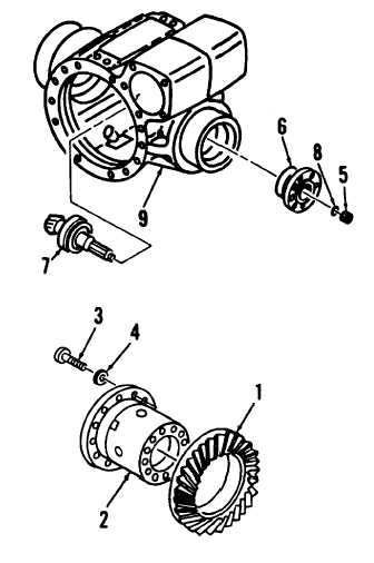
7.
Install new O-ring (8) onto bevel gear shaft (18).
Install nut (5) and torque to 192 to 222 ft-lbs. (260
to 300 N•m).
8.
Install large bevel gear (1) onto differential case (2).
9.
Apply loctite to threads of twelve new bolts (3) and
install with washers (4). Torque bolts to 46 to 53 ft-
lbs. (69 to 72 N•m).
10. Install differential gear case (para. 4-32).
11. Measure from center-line of axle to shoulder of
closed end pinion bearing to determine bevel pinion
(7) mounting distance. Compare this measurement
with factory recommended mounting distance
recorded during removal.
12. Remove bevel pinion components and add or
subtract shims (14, 16) until actual mounting
distance matches factory recommended mounting
distance.
FOLLOW-ON MAINTENANCE:
None
END OF TASK
4-92
|