| |
TM 10-3930-664-24
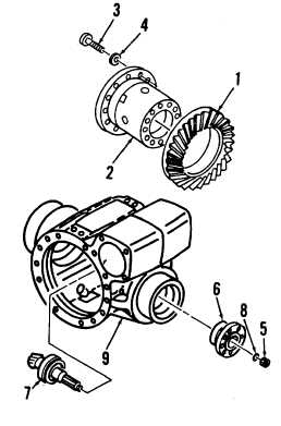
4-33. BEVEL GEAR REPLACEMENT (REAR AXLE ASSEMBLY)
This task covers: Removal, Cleaning, Inspection, and Installation
INITIAL SETUP:
Tools and Test Equipment:
Equipment Condition:
General Mechanics Tool Kit (1, App. E)
Differential gear case removed
Torque Wrench (32, App. E)
(para. 4-32)
Puller Kit (26, App. E)
3/4" Drive Socket Set (55, App. E)
Arbor Press (25, App. E)
Materials / Parts:
Loctite No. 270 (22, App. C)
Bolt, Item 3 (12 ea.)
O-Ring, Item 8 (1 ea.)
Shim, Item 14 (As required)
Shim, Item 16 (As required)
A. REMOVAL
1.
Remove large bevel gear (1) from differential case
(2) by removing twelve bolts (3) and washers (4).
Discard bolts.
2.
Remove nut (5) and pull flange (6) off assembled
bevel pinion (7). Remove and discard O-ring (8).
3.
Using a bearing puller, press assembled bevel
pinion (7) toward inside of differential housing (9).
Remove assembled bevel pinion from axle housing.
4.
Bevel pinion (7) is stamped with a factory
recommended mounting
distance (center-line of
axle to shoulder of closed end bearing). Note and
record this distance for use during installation.
4-90
|