| |
TM 10-3930-664-24
4.
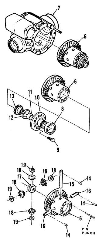
Carefully remove assembled differential gear case
(6) from axle housing (7).
5. Remove bearing cone (8) from gear case (6).
6. Remove twelve bolts (9) from sprocket (10).
Remove sprocket, thrust bearing (11), friction
washer (12), and differential gear (13) from gear
case (6).
NOTE
Shafts (15, 16) are marked with a part
number on one end. Holes for pins
(14) are located on marked end.
Two different lengths of shaft are
used; one long (15) and two short
(16).
7. Using a soft head hammer and pin punch, drive pins
(14) fully into shafts (15, 16). Depth from face of
gear case (6) to top of pins shall be 41 mm (see
figure).
8. Extract shafts (15, 16) from gear
case
(6).
Remaining parts will fall loose into case.
9. Remove pins (14) from shafts (15, 16).
10. Remove shaft retainer (17), differential pinions (18),
and friction washers (19) from gear case (6).
B. CLEANING
Clean components in accordance with paragraph 1-24.
C. INSPECTION
Inspect components in accordance with paragraph 1-24.
D. INSTALLATION
1. Insert long shaft (15) part way into gear case (6).
Install one friction washer (19) and pinion gear (18)
onto shaft.
2. Push shaft (15) through shaft retainer (17) and install
second pinion gear (18) and friction washer (19).
4-72
|