| |
TM 10-3930-664-24
7.
Inspect valve stem tip for flatness. If required,
resurface valve stem tip.
8.
Grind valve seat as follows:
a.
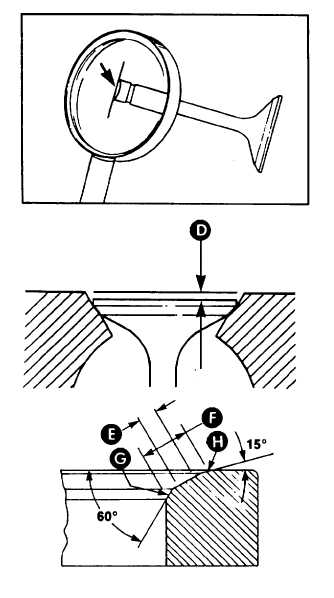
Install valve in designated bore and
measure
valve
depth
(dimension
D).
Valve depth is the distance from valve
face to head deck. Record depth and
remove valve from bore.
b.
Grind valve seat to remove scores,
scratches, and burns. Ensure seat
angles are maintained. Intake angle must
be 30 degrees. Exhaust angle must be 45
degrees.
c.
Reinstall valve and measure valve depth
again. Record depth as D1.
d.
Calculate grind depth (GD) by
subtracting dimension D from dimension
D1. Grind valve seat until GD equals
0.010 in (0.254 mm).
D1 D = 0.010 inch (GD)
e.
Reinstall valve seat and measure valve
depth again. Depth shall be 0.0389 to
0.0598 in (0.99 to 1.52 mm). Replace
valve if out of limits.
f.
Repeat steps a through e for remaining
valves.
9.
Apply a light coat of lapping compound to each
valve. Lap valves to companion seats.
10.
Remove valves. Clean lapping compound from
valves and seats.
11.
Measure valve seat width indicated by lapped
surface (dimensions E AND F). Width E shall
not exceed 0.060 in. (1.5 mm). Width F shall
nor exceed 0.080 in. (2.0 mm).
12.
Grind areas G and H, as required, to center seat
on valve face. Grind area G with a 60 degree
stone and area H with a 15 degree stone.
4-12
|