| |
TM 10-3930-664-24
15.
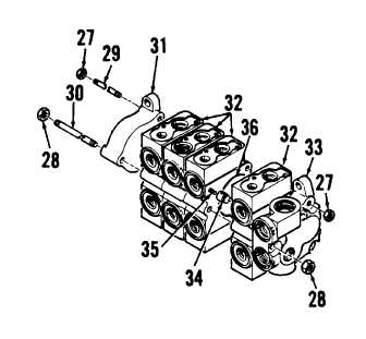
Remove nuts (27, 28) from tie rods (29, 30).
Remove tie rods and separate outlet housing
(31), spool housings (32), and inlet housing (33).
16.
Remove four poppets (34) and springs (35) from
spool housings (32). Remove and discard O-
rings (36).
B. CLEANING
Clean
directional
control
valve
components
in
accordance with paragraph 1-24.
C. INSPECTION
1.
Conduct overall inspection of directional control
valve components in accordance with paragraph
1-24.
2.
Inspect spools and spool bores for damage or
deformation. Check for evidence of excessive
or uneven wear.
3.
Inspect outlet, inlet, and spool housings for
cracks. Inspect mating surfaces for damage that
may prevent a proper seal. Check for evidence
of leakage.
D. REPAIR
Repair of the directional control valve assembly consists
of removal and replacement of defective, deformed, or
damaged components.
E. ASSEMBLY
1.
Lubricate new O-rings (36) with clean lubricating
oil and install into inlet housing (33) and spool
housings (32).
2.
Insert four poppets (34) and springs (35) into
spool
housings
(32)
as
each
section
is
assembled.
3.
Mate outlet housing (31), spool housings (32),
and inlet housing (33). Inset tie rods (29, 30)
and install nuts (27, 28). 3. Torque nuts (27) to
13 to 15 ft-lbs (18 to 20 Nm). Torque nut (28) to
30 to 36 ft-lbs (41 to 49 Nm).
3-208
|