| |
TM 10-3930-664-24
3-63. DIRECTIONAL CONTROL VALVE ASSEMBLY REPAIR
This task covers: Disassembly, Cleaning, Inspection, Repair, and Assembly
INITIAL SETUP:
Tools and Test Equipment:
Materials / Parts:
General Mechanics Tool Kit (1, App. E)
Lubricating Oil (16, App. C)
Vise (30, App. E)
Loctite 242 (20, App. C)
Drain Pan (10, App. E)
Roll Pin, Item 3 (4 ea.)
Torque Wrench (32, App. E)
O-Ring, Item 7 (I ea.)
O-Ring, Item 9 (1 ea.)
Equipment Condition:
O-Ring, Item 13 (3 ea.)
Wiper Seal, Item 16 (4 ea.)
Directional control valve
O-Ring, Item 17 (4 ea.)
removed (para. 2-150)
Wiper Seal, Item 25 (4 ea.)
O-Ring, Item 26 (4 ea.)
O-Ring, Item 36 (5 ea.)
O-Ring, Item 39 (1 ea.)
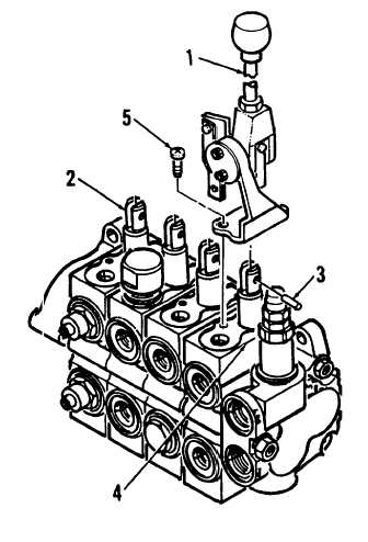
A. DISASSEMBLY
1.
Place directional control valve assembly in a vise
for disassembly.
2.
Detach valve handles (1) from spools (2) by
driving out roll pins (3). Discard roll pins.
3.
Remove valve handles (1) from spool housings
(4) by removing screws (5).
3-206
|