| |
TM 10-3930-664-24
F.
ASSEMBIY
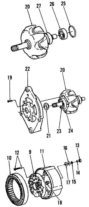
1.
Insert one lead of excitation winding into groove in
collector rings (27). Using an arbor press, install
collector rings onto rotor (20).
2.
Solder leads of excitation winding to collector rings
(27). Turn down soldered joint on both rings until
rings are even.
3.
Press bearing (26) onto rotor (20). Install new O-ring
(25).
4.
Press bearings (23) into drive end shield (22). Install
cover plate (24) and secure using four screws (19).
5.
Place drive end shield (22) on arbor press. Insert
rotor (20) into bearing (23) and press into place.
6.
Install insulator caps (18) on B+ and D+ terminals
mounted to rectifier plate (9). Install rectifier plate (9)
into ring end shield (11).Secure rectifier plate using
three screw and washer sets (12).
7.
Install insulators (17), spring washers (15),
insulating washers (16), washers (14), and nuts (13).
8.
Place stator (10) against rectifier plate (9). Match
markings on stator, rectifier plate, and ring end
shield (11).
CAUTION
Do not use excessive solder. Too much
solder can cause short-circuit bridges.
9.
Solder connection wires of stator (10). Ensure
connection wires will not contact rotor once rotor is
installed.
3-93
|