| |
TM 10-3930-664-24
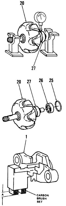
14. Mount rotor (20) in test stand as shown in figure.
Using dial indicator, conduct true-running test at the
following points:
- OD of rotor (20)
- OD of collector rings (27)
Maximum error for rotor (20) is 0.05 mm.
Maximum error for collector rings (27) is
0.03 mm.
15. Remove rotor (20) from test stand.
16. Remove and discard O-ring (25). Using bearing
puller, remove bearing (26) from rotor (20).
17. Unsolder leads of excitation winding from collector
rings (27). Using bearing puller, remove collector
rings from rotor (20).
C.
CLEANING
Clean alternator components in accordance with para-
graph 1-24.
D.
INSPECTION
1.
Inspect alternator components in accordance with
paragraph 1-24.
2.
Inspect carbon brushes on transistor regulator (1) for
obvious damage. Brushes shall project 0.27 inches
(minimum).
E.
RFPAIR
CAUTION
Do not allow solder to contact brushes.
1.
If brush set is damaged or brushes project less than
0.27 inches, unsolder brush set and replace. New
brushes shall project 0.39 inches. Check brushes
for freedom of movement after installation.
2.
Repair of the alternator consists of removal and
replacement of defective, deformed, or damaged
components.
3-92
|