| |
TM 10-3930-664-24
B.
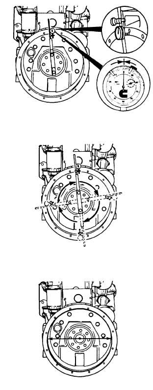
HOUSING FACE ALIGNMENT CHECK
1.
Attach dial indicator to crankshaft as shown in
figure. Indicator extension bar must be rigid for
accurate readings. If the extension bar sags or
the indicator slips, readings will not be accurate.
CAUTION
Dial indicator tip must not enter cap
screw holes or dial indicator will be
damaged.
2.
Move dial indicator to 12 o’clock position. Adjust
dial until needle points to zero.
NOTE
Each time a position is measured, the
crankshaft must be pushed toward front
of engine to eliminate crankshaft end
clearance.
3.
Slowly rotate crankshaft. Record dial readings
at 3, 6, and 9 o’clock positions.
4.
Continue to rotate crankshaft until dial indicator
is at 12 o’clock position. Check indicator to
ensure needle points to zero.
5.
Calculate total indicator reading (TIR) as follows
(numbers are for example only):
12 O’Clock Reading -
+ 0.000 IN.
+
3 O’Clock Reading =
+ 0.003 IN.
+
6 O’Clock Reading =
- 0.002 IN.
+
9 O’Clock Reading =
+ 0.003 IN.
Equals TIR
+ 0.005 IN.
6.
TIR reading for face alignment check shall not
exceed 0.008 inch. If TIR exceeds 0.008 inch,
housing face is out of alignment and housing
must
be
replaced.
3-41
|