| |
TM 10-3930-664-24
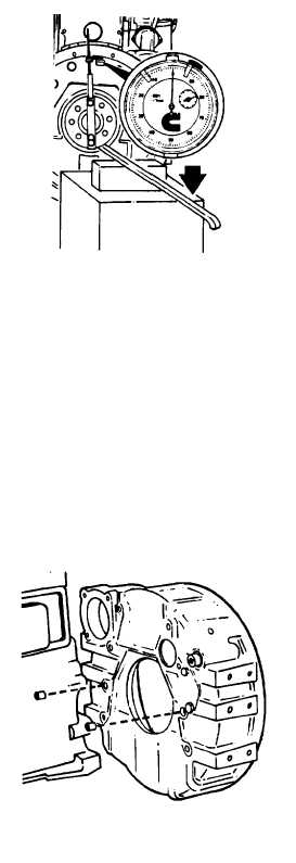
CAUTION
Use care when raising crankshaft to
prevent damage.
Do
not
force
crankshaft beyond the point where
bearing clearance has been removed.
6.
Using a floor mounted support and padded pry
bar, raise rear of crankshaft to its upper limit.
7.
Record new dial reading at 12 o’clock position.
New
reading
indicates
vertical
bearing
clearance.
8.
Calculate a "total horizontal" value by subtracting
the 3 o’clock reading (step 3) from the 9 o’clock
reading:
9 o’clock reading
- 3 o’clock reading
= total horizontal value
9.
Calculate a "total vertical" value by adding the 12
o’clock reading (step 3) to the vertical bearing
clearance (step 7):
12 o’clock reading
+ vertical bearing clearance
= total vertical value
10.
Mark the "total horizontal" value on horizontal
side of adjacent chart. Mark the total vertical"
value on vertical side.
11.
Using a straight edge, find the intersection point
of the two values. Intersection point must fall
within shaded area of chart.
12.
If intersection falls outside shaded area on chart,
housing concentricity is not within specifications.
Remove flywheel housing (paragraph C) and
remove dowel rings.
13.
After dowel rings are discarded, reinstall flywheel
housing. Tighten capscrews enough to hold
housing in place, but loose enough to allow small
movement when struck lightly with a mallet.
14.
Recheck concentricity. Torque capscrews.
3-40
|