| |
TM 10-3930-664-24
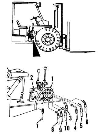
2-150. DIRECTIONAL CONTROL VALVE REPLACEMENT
This task covers: Removal, Cleaning, Inspection, and Installation
INITIAL SETUP:
Tools and Test Equipment:
References:
General Mechanics Tool Kit (1, App. E)
LO 10-3930-664-12
Drain Pan (10, App. E)
Vise (30, App. E)
Materials / Parts:
Personnel Required:
O-Ring, Item 25 (2 ea.)
2 Personnel
O-Ring, Item 26 (1 ea.)
O-Ring, Item 27 (2 ea.)
O-Ring, Item 28 (1 ea.)
O-Ring, Item 29 (1 ea.)
O-Ring, Item 30 (1 ea.)
O-Ring, Item 31 (1 ea.)
A. REMOVAL
NOTE
Place drain pan beneath hydraulic pump
hoses when disconnecting to catch
residual fluids.
1.
TAG AND DISCONNECT HOSE ASSEMBLIES
(1, 3 THROUGH 10) FROM DIRECTIONAL
CONTROL VALVE ASSEMBLY (2).
a.
Tag and disconnect large hose assembly
(I) from directional control valve assembly
(2).
b.
Tag and disconnect hose assemblies (3,
4, 5, 6) from top ports of directional control
valve assembly (2).
c.
Tag and disconnect hose assemblies (7,
8, 9, 10) from bottom ports of
directional control valve assembly (2).
2-395
|