| |
TM 10-3930-664-24
2.
DISCONNECT
CIRCUIT
TO
BE
TESTED
FROM POWER SOURCE.
3.
CONNECT MULTIMETER PROBES TO BOTH
TERMINALS OF CIRCUIT BEING TESTED.
OBSERVE METER NEEDLE MOVEMENT.
a.
If needle swings to far right (over "0" at top
of
scale),
circuit
being
tested
has
continuity.
b.
If needle does not move, circuit is open.
c.
If needle jumps or flickers, there is a loose
connection in circuit being tested.
B.
SHORT CIRCUIT TESTING
1.
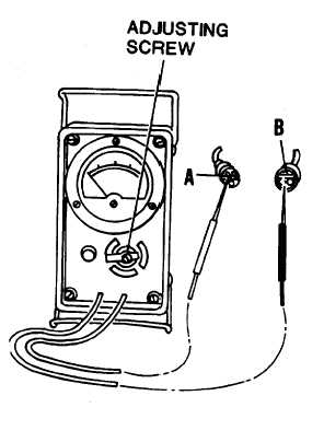
SET UP AND ZERO MULTIMETER.
a.
Before
using
multimeter,
check
mechanical zero of meter. If meter pointer
is not exactly over zero line, reset pointer
by rotating adjusting screw.
2.
DISCONNECT
CIRCUIT
TO
BE
TESTED
FROM POWER SOURCE.
3.
CONNECT
MULTIMETER
PROBES
TO
CIRCUITS BEING TESTED.
a.
Connect one meter probe to first circuit
(see A in figure).
b.
Connect other meter probe to second
circuit (see B).
4.
OBSERVE METER NEEDLE MOVEMENT.
a.
If needle swings to far right (over "0" at top
of scale), circuits being tested are shorted.
b.
If needle does not move, circuits are not
shorted.
c.
If needle jumps or flickers circuits are
intermittently short circuited.
2-233
|