| |
TM10-3930-660-34
16-18.1. HYDRAULIC JOYSTICK CONTROL VALVE - REPAIR
This task covers:
a.
Disassembly
b.
Cleaning
c.
Inspection
d.
Assembly
Initial Setup
Tools
Materials/Parts
Tool Kit, Automotive Mechanics
Backup Ring (25)
Grease (App. B, Item 11)
Shop Equipment, Automotive
Loctite 271 (App. B Item 43)
Maintenance, Common %2
O-rings (11, 26 and 27)
Less Power
Seal (12)
Transmission/Hydraulic Lubricating
Equipment Condition
Oil (App. B, Item 35)
Hydraulic joystick control valve
removed, TM10-3930-660-20.
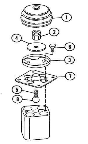
DISASSEMBLY
1.
REMOVE BOOT (1) BY CAREFULLY PRYING
IT FROM GROOVE IN SPECIAL NUT (2)
AND OUT FROM UNDER BOOT CLAMP (3).
2.
REMOVE SPECIAL NUT (2) AND PIVOT
PLATE (4) FROM PIVOT BOLT (5).
NOTE
Plunger capsules are under spring
compression. Hold mounting plate (7)
down and remove capscrews (6) in even
increments.
3.
REMOVE TWO CAPSCREWS (6), BOOT CLAMP
(3) AND MOUNTING PLATE (7).
4.
PUSH PIVOT BOLT (5) DOWN OUT OF
MOUNTING PLATE (7), USING CARE NOT
TO LOSE BALL (8).
16-117
|