| |
TM10-3930-660-34
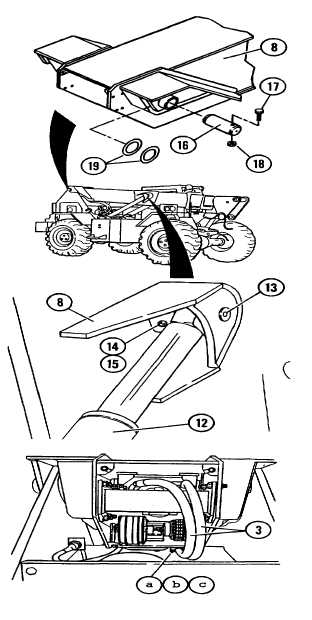
16-12.BOOM ASSEMBLY - REPLACE (Cont’d)
c.
Secure boom pivot pin (16) to vehicle frame with
capscrew (17) and new locknut (18).
d.
Repeat steps lb and lc for other pivot pin (16).
2.
PLACE JACKSTAND OR SUPPORT ON FRONT OF
VEHICLE DECK.ADJUST SUPPORT SO BOOM ASSEMBLY
(8) IS LEVEL WHEN LOWERED.
3.
CAREFULLY LOWER BOOM ASSEMBLY (8) WITH HOIST
AND SLING UNTIL FRONT OF OUTER BOOM SECTION IS
ON JACKSTAND OR SUPPORT.
4.
SECURE HYDRAULIC HOSES (3) TO BOTTOM OF BOOM
ASSEMBLY WITH NEW LOCKNUTS (a), CAPSCREWS (b),
AND CLAMP HALVES (c).
5.
CONNECT ROD ENDS OF BOOM HOIST CYLINDERS (12)
TO BOOM ASSEMBLY (8).
a.
Reposition slings to front of outer boom section.
b.
Lift boom assembly (8) until cylinder pivot pin holes of
boom assembly (8) are just above cab.
c.
Lift boom hoist cylinders (12) into position and support
cylinders.
CAUTION
Use hoist and sling to make final alignment with
cylinder rod eye and pivot pin hole. Do not use
the joystick to make final alignment; damage to
rod eye bushing could result.
NOTE
One boom hoist cylinder (12) will begin to extend
before the other. Install this cylinder first. Second
cylinder will begin to extend after first cylinder is
connected.
16-54
|