| |
TM10-3930-660-34
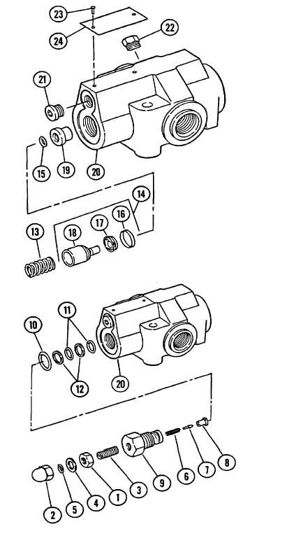
16-7. FRAME TILT/BRAKES RELIEF VALVE - REPAIR (Cont’d)
h.
Remove retainer (16), screw (17) and
poppet (18) if necessary.
i.
Do not remove seat (19) from body (20).
2.
REMOVE
PLUGS
(21
AND
22)
IF
NECESSARY.
3.
REMOVE
TWO
SCREWS
(23)
AND
NAMEPLATE (24) IF NECESSARY.
CLEANING
See Cleaning Instructions, para.2-10.
INSPECTION
See Inspection Instructions, para 2-11.
ASSEMBLY
NOTE
Wipe all sealing surfaces of valve
clean and dry. .Apply film of clean
hydraulic oil to all seals as they
are installed.
1.
IF REMOVAL WAS NECESSARY, INSTALL
NAMEPLATE (24) AND TWO SCREWS (23).
2.
IF REMOVAL WAS NECESSARY, INSTALL
PLUGS (21 AND 22).
3.
ASSEMBLE AND INSTALL RELIEF VALVE
(1-19) INTO BODY (20).
a.
Install new O-ring (15) in seat (19).
b.
If removal was necessary, install screw
(17) and retainer (16) on poppet (18).
c.
Install poppet assembly (14) and spring
(13) into body (20).
d.
Install two new O-rings (11) and O-ring
(10) on cap (9).Ensure that back-up rings
(12) are correctly positioned.
16-32
|