| |
TM10-3930-660-34
8-5.
FRONT DIFFERENTIAL CARRIER ASSEMBLY - REPLACE/REPAIR/ADJUST (Cont’d)
DISASSEMBLY
1.
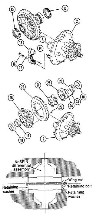
REMOVE DIFFERENTIAL AND RING GEAR
ASSEMBLY FROM CARRIER (2).
a. Use a center punch and hammer to
mark one carrier leg (A) and
bearing cap (13) to enable correct
matching at reassembly.
b. Remove cotter pins (14) holding
two bearing adjusting rings (15)
in position. Discard cotter pins
(14).
c. Remove two capscrews (16) and two
flatwashers (17) from each of two
bearing caps (13).
d. Remove two bearing caps (13) and
two bearing adjusting rings (15).
e. Use a sling to lift the main
differential and ring gear
assembly from the carrier. Place
the assembly on a work bench.
f.
Remove two bearing cups (18).
g. Remove flange case half bearing
cone (19) and plain case half
bearing cone (20) with a suitable
puller.
2.
DISASSEMBLE NO-SPIN DIFFERENTIAL
(21) AND RING GEAR (22) ASSEMBLY.
a. If matching marks on the case
halves of the differential are
not visible, mark each case half
with a center punch and hammer.
The match marks are to ensure
proper part orientation at
assembly.
b. Secure the no-spin differential
(21) with a bolt, a wing nut, and
two flatwashers. See Materials/Pa!ts
heading for retaining hardware
dimensions.
8-12
|