| |
TM10-3930-660-34
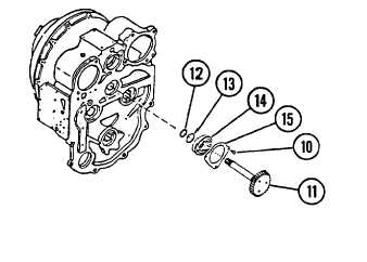
7-7. TRANSMISSION INPUT SHAFT - REPLACE/REPAIR (Cont’d)
2.
REMOVE THREE CAPSCREWS (10) AND
TRANSMISSION INPUT SHAFT (11) AS AN ASSEMBLY.
DISASSEMBLY
1.
REMOVE SEAL RING (12) FROM INPUT SHAFT (11).
2.
REMOVE SNAP RING (13) AND BALL BEARING (14).
3. REMOVE BEARING RETAINER (15).
CLEANING
See Cleaning Instructions, para. 2-10.
ASSEMBLY
1.
INSTALL BEARING RETAINER (15) ON
INPUT SHAFT (11). ENSURE THAT FLAT
SIDE OF BEARING RETAINER (15) FACES AWAY FROM INPUT SHAFT (11) GEAR.
2.
INSTALL BALL BEARING (14) AND SNAP RING (13).
3.
INSTALL SEAL RING (12).
INSTALLATION
NOTE
When installing cap screws (10), apply Loctite #242.
1.
INSTALL INPUT SHAFT (9) AS AN ASSEMBLY.
a. Apply grease to seal ring (12) to center it on input shaft (11).
b. Install input shaft (11) as an assembly through bore in back of
front cover assembly (1). Ensure that bearing retainer (15) is
placed with flat side against front cover (1).
c. Apply Loctite #242 to threads of three cap screws (10) and
install.
2.
INSTALL FRONT COVER ASSEMBLY (1),
TORQUE CONVERTER (2) AND FRONT
HOUSING (3) AS A UNIT TO MAIN
CASE.
a. Place new gasket (9) on main case.
b. Attach a hoist with sling, or other
suitable lifting device, to front cover
assembly (1), torque converter (2) and
front housing
c. Install four capscrews (8), three
capscrews (7) and capscrews (4-6)
which secure unit to main case. (3) as a
unit. Lift unit into position on main case.
3.
INSTALL TRANSMISSON ASSEMBLY,
PARA. 7-4.
7-48
|