| |
TM10-3930-660-34
7-4.
TRANSMISSION ASSEMBLY - REPLACE/REPAIR (Cont’d)
WARNING
Ensure that retainer ring (98) is secure in groove before
spring compressor tool is removed from retainer (97) to
prevent springs (99) from flying out. Failure to follow this
precaution could cause personal injury.
f.
Press down on spring compressor tool and
retainer (97) to allow installation of retainer ring
(98). Slowly remove spring compressor tool.
CAUTION
Carefully handle clutch plates (95) so graphite coating
doesn’t flake off. Failure to follow this precaution could
cause equipment damage.
g.
Install
four
clutch
plates
(95)
and
four
separator plates (96) into shaft assembly (88).
Begin with a separator plate (96) and then a
clutch plate (95). Continue by alternating
plates. The last plate must be a clutch plate
(95).
NOTE
The separator plates (96) have external teeth and clutch
plates (95) have internal teeth. The plates do not have a
right or wrong side for installation.
h.
Install clutch plate retainer (94) and snap ring
(93) on shaft assembly (88).
i.
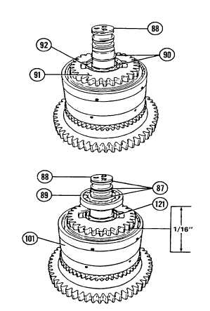
Install appropriate pair of alignment bars
between weld gear (91) and piston (101), as
required, to hold weld gear (91) off piston
(101). Use either narrow or wide side of bars
to ensure that weld gear (91) is held off piston
(101) 1/16" and at the same time engages all
clutch plates (95).
7-29
|