| |
TM10-3930-660-34
Section II. EQUIPMENT DESCRIPTION AND DATA
1-7.
LOCATION AND DESCRIPTION OF MAJOR COMPONENTS.
a.
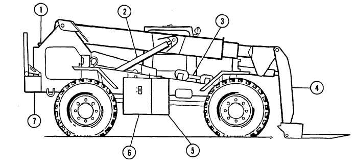
Right Side View of the 6KVRRTFL.
(1)
Radiator. Contains coolant which provides engine cooling.
(2)
Boom Hoist Cylinder. Raises and lowers the boom.
(3)
MLRS Lifting Tool and Stop Tube (shown in storage position). The stop tube prevents the lifting tool
from moving too far back on the forks and prevents the MLRS pod from contacting the frame or vehicle
wheels when in the carry position.
(4)
MLRS Attachment. This attachment is required for MLRS and forklift operations. The MLRS attachment
can be raised to a horizontal position, creating a low profile and extended reach configuration. This
configuration is useful in loading and unloading munitions from transport vehicles and containers.
(5)
Fuel Tank. Contains diesel fuel for engine operation.
(6)
Hydraulic Oil Reservoir. Contains hydraulic fluid for the hydraulic system.
(7)
Frame and Counterweight. The frame is a heavy-duty design constructed of 1-3/16 inch thick steel
plates. The frame is equipped with tie-down lugs meeting air transport specifications, tow lugs, a pintle
hook, and a 3,600 lb. counterweight. The counterweight is removable so that axle loading can be
adjusted to meet air transport requirements for some aircraft.
(8)
Load Backrest (shown in storage position). Used to rest a load during non-MLRS operations. The
backrest can be attached to the fork carriage and serves as a backstop or support for materials being
carried on the forks.
1-3
|