| |
TM10-3930-660-34
6-9.
ELECTRIC JOYSTICK ASSEMBLY - REPAIR/TEST/ADJUST (Cont’d)
e.
Turn starter switch to the RUN position but do not
start the engine, TM10-3930-660-10.
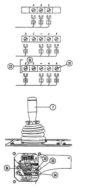
f.
Slowly move joystick handle (7) rearward until indicator
light (32) just comes on. Ammeter reading should be
between 300 and 340 ma.
NOTE
During step g., Turn "threshold" control (33) counterclockwise to
lower ammeter reading, and clockwise to raise ammeter reading.
g.
If reading in step f. was not within limits of 300 to 340
ma., adjust "threshold" control (33) and repeat step f
until ammeter reads approximately 320 ma.
h.
Move joystick handle (3) fully rearward and observe
ammeter reading. Reading should be between 600 and
640 ma.
NOTE
During step i., turn "max out" (34) control counterclockwise to lower
ammeter reading, and clockwise to raise ammeter reading.
i.
If reading in step h. was not within limits of 600 to 640
ma., adjust "max out" control (34) and repeat step h
until ammeter reads approximately 620 ma.
j.
Turn starter switch off, TM10-3930-660-10.
k.
Disconnect leads of ammeter. Secure electrical lead
#55 to terminal A of bottom circuit board (22) with screw
(31).
6-40
|