| |
TM10-3930-660-34
6-9.
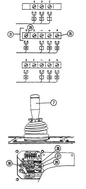
ELECTRIC JOYSTICK ASSEMBLY - REPAIR/TEST/ADJUST (Cont’d)
q. Move joystick handle (7) fully to the right and observe ammeter
reading. Reading should be between 600 and 640 ma.
NOTE
During step r., turn "max out" control (28) counterclockwise to lower
ammeter reading, and clockwise to raise ammeter reading.
r.
If reading in step q. was not within limits of 600 to 640
ma., adjust "max out" control (28) and repeat step q.
until ammeter reads approximately 620 ma.
s.
Turn starter switch off, TM10-3930-660-10.
t.
Disconnect leads of ammeter. Secure electrical lead
#54 to terminal B of top circuit board (21) with screw
(29).
u.
Repeat steps 3a through 3j and check that current
readings are still within limits. Readjust "threshold" (27)
and "max out" (28) controls as required.
4.
MEASURE CURRENT FLOW TO LOWER CIRCUIT BOARD
(22). IF NECESSARY, ADJUST "THRESHOLD" AND "MAX
OUT" CONTROLS.
a.
Connect joystick to cab wiring harness (1).
b.
Loosen screw (31) at terminal A of bottom circuit board
(22) and disconnect electrical lead #55.
c.
Connect positive (+) lead of suitable ammeter to terminal
A of bottom circuit board (22).
d.
Connect negative (-) lead of ammeter to disconnected
electrical lead #55.
6-39
|