| |
TM10-3930-660-34
6-9.
ELECTRIC JOYSTICK ASSEMBLY - REPAIR/TEST/ADJUST (Cont’d)
f.
Install two screws (9) and two nuts (10) at top
of handle sections (7).
g. Place boot (8) on handle sections (7).
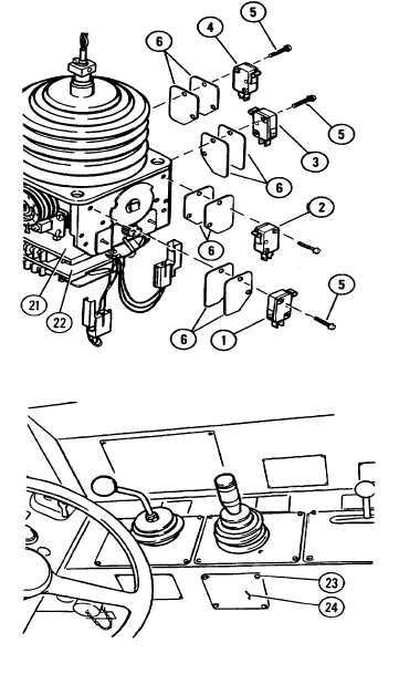
INSTALLATION OF KICROSWITCHES
NOTE
Plug with red and black leads from upper circuit board (21)
connects to microswitch (1).
Plug with white, blue, and yellow leads from upper circuit board
(21) connects to microswitch (2).
Plug with red and black leads from lower circuit board (22)
connects to microswitch (3).
Plug with white, blue, and yellow leads from upper circuit board
(22) connects to microswitch (4).
INSTALL MICROSWITCHES (1) THROUGH (4).
a. Secure microswitch (1) and two spacers (6) with two
screws (5).
b. Connect plug to microswitch (1)
c. Repeat steps a and b for microswitches (2) through
(4).
TESTING AND ADJUSTMENT OF JOYSTICK
“THRESHOLD" AND “MAX OUTS” SETTINGS
1.
INSTALL ELECTRIC JOYSTICK, TM10-3930-660-20.
2.
REMOVE FOUR CAPSCREWS (23) AND PLATE (24).
6-36
|