| |
TM10-3930-660-34
6-5.
BOOM ELECTRICAL BOX ASSEMBLY - REPAIR (Cont’d)
ASSEMBLY
1.
CONNECT JUMPER TERMINALS (21) TO
PROPER TERMINALS ON LOWER TERMINAL
STRIP (13).
2.
INSTALL TERMINAL STRIPS (13).SECURE
WITH EIGHT SCREWS (18), NUTS (19) AND
NEW LOCKWASHERS (20).
3.
INSTALL WIRE ASSEMBLY (18).
a. Connect wire assembly (18) to terminal strips
(3 and 10), as shown.
b. Attach to panel using screw (16) and new lockwasher
(17).
4.
INSTALL CABLES (9, 10 AND 11).
a. Install grommet (14 or 15), as applicable, on cable to be
installed.
b. Carefully push cable through entrance in enclosure and
work grommet (14 or 15) into place in cable entrance.
c. Connect cable wires to proper terminals on terminal strip
(13).
d. Install new cable ties (10), as necessary.
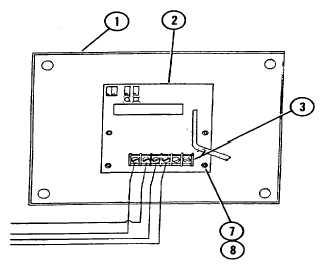
5.
INSTALL AUTOMATIC LEVELER CIRCUIT BOARD (2).
a. Secure circuit board (2) to enclosure cover (1),
using four screws (7) and nuts (8).
b. Install connector (6), using four screws (4) and
new lockwashers (5).
c. Connect four wires to terminal
strip (3). Observe tags placed
6.
INSTALL ENCLOSURE COVER (1) USING FOUR
board removal
SCREWS (NOT SHOWN).
7.
CONNECT NEGATIVE BATTERY CABLE, during circuit
TM10-3930-660-20.
6-21
|