| |
TM10-3930-660-34
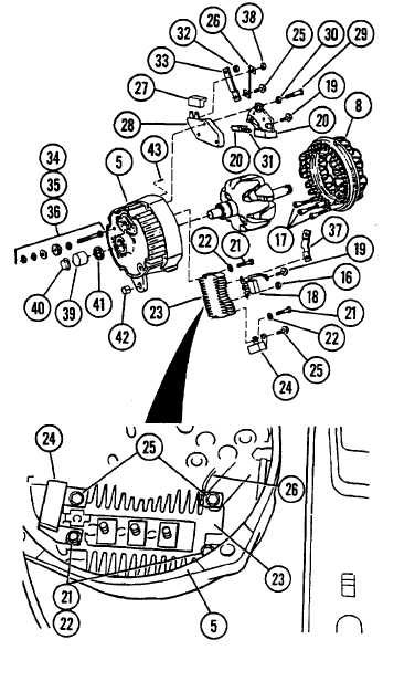
6-3. ALTERNATOR - REPAIR/TEST (Cont’d)
e. Place regulator (28), brush
springs (31), and brush and
holder assembly (20) inside frame
(5).
f. Install screw (29), new lockwasher
(30), and insulated screw (19) to
secure regulator (28), brush spring
(31), and brush and holder assembly
(20) to frame (5).
d. Install rubber cover (27) to
terminals of regulator (28).
e. Place rectifier bridge (23) inside
frame (5).
NOTE
Holes for screw and lockwasher assemblies
(25) are located on the rectifier bridge
(23), closest to center of frame (5).
One assembly (25) secures the upper
contact of capacitor (24). The other
assembly (25) secures wire lead (26).
f. Secure wire lead (26) and top
contact of capacitor (24) to
rectifier bridge (23) with two new
screw and lockwasher assemblies
(25).
NOTE
Holes for screws (21) and springwashers
(22) are located on the rectifier
bridge (23), closest to outside of frame
(5). One of the two screws (21) secures
the lower contact of capacitor (24).
g. Secure rectifier bridge (23) to
frame (5) with two screws (21) and
two new spring washers (22).
i. Secure diode trio (18) to brush and
holder assembly (20) with insulated
screw (19).
6-9
|