| |
TM10-3930-660-34
6-3. ALTERNATOR - REPAIR/TEST (Cont’d)
e. If both readings on same set of
connectors are either high or low,
the associated diode is faulty and
entire diode trio must be replaced.
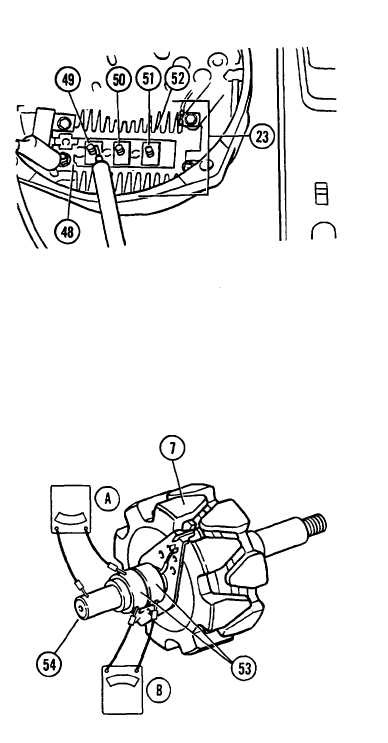
2. TEST RECTIFIER BRIDGE (23).
a. Connect ohmmeter from grounded heat
sink (48) to diode terminal (49)
and note resistance reading.
b. Reverse ohmmeter leads or reverse
meter polarity and again note
resistance reading.
c. At one polarity, resistance reading
should be low and at the other
polarity, resistance reading should
be very high, if diode is good. If
diode is faulty, both readings will
be either low or high.
d. Repeat above sequence between
grounded heat sink (48) and diode
terminals (50 and 51), and then
between insulated heat sink (52)
and each diode terminal (49, 50 and
51).
e. If any set of readings indicates a
faulty diode, replace complete
rectifier bridge (23).
3. TEST ROTOR (7) FOR SHORT OR OPEN
CIRCUITS.
a. Connect ohmmeter between slip
rings (53), in turn, and rotor
shaft (54) (connection A). Observe
resistance reading on ohmmeter.
b. Resistance reading should be high
(infinite). If not, rotor (7) is
defective and must be replaced.
c. Connect ohmmeter leads across slip
rings (53) (connection B). Observe
resistance reading on ohmmeter.
6-6
|