| |
TM10-3930-660-34
6-3. ALTERNATOR - REPAIR/TEST (Cont’d)
f. If necessary, remove nut (32),
connector (33), and battery
terminal assembly parts (34).
g. If necessary, remove relay terminal
cap (35), relay terminal assembly
parts (36), and connector (37).
h. If necessary, remove nut (38) and
wire lead (26) from regulator (28).
NOTE
If roller bearing (39) is not being
removed, apply pressure sensitive tape
over it for protection against dirt. Do
not use friction tape or other tape that
will leave a residue behind.
INSPECTION
i. If necessary for replacement,
1. INSPECT BEARINGS (14 AND 39) FOR ROUGH
push roller bearing (39) out of
ROTATION OR VISIBLE DAMAGE.
frame (5) and remove seal (41) and
plug (40). Discard seal (41).
2. INSPECT BRUSHES (20) FOR EXCESSIVE
WEAR.
j. If necessary, remove bushing
(42) and pin (43) from frame (5).
3. INSPECT BRUSH SPRINGS (31) FOR
DISTORTION OR DISCOLORATION
CLEANING
TESTING
1. CLEAN BRUSHES USING SOFT, DRY CLOTH.
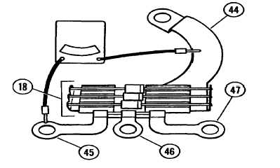
1. TEST DIODE TRIO (18).
2. CLEAN SLIP RINGS ON ROTOR (7).
a. Remove diode trio (18).
a. Place rotor (7) in a lathe, with
slip ring of shaft free.
b. Connect ohmmeter between diode trio
single connector (44) and each of
b. While rotor is spinning in lathe,
the other connectors (45, 46, and
hold No. 00 sandpaper or 400 grit
47) in turn. Observe resistance
silicon carbide paper against slip
reading on ohmmeter.
ring surface.
c. Reverse ohmmeter leads, or reverse
c. After polishing slip rings, clean
meter polarity, and repeat STEP b,
using low pressure (15 psi
above.
maximum) compressed air.
d. At one polarity, resistance reading
d. Clean ball bearing (14) in dry
should be low and at the other
cleaning solvent to remove
polarity, resistance reading should
lubricant.
be very high, if diodes are good.
6-5
|