| |
TM10-3930-660-34
4-6.
TURBOCHARGER ASSEMBLY - REPAIR
This task covers:
a. Disassembly
b. Cleaning
c. Inspection
d. Assembly
Initial Setup
Tools
Materials/Parts
Tool Kit, Automotive Mechanics
Capscrews (18)
Crocus Cloth (App. B, Item 4)
Shop Equipment, Automotive
Engine Lubricating Oil (App. B,
Maintenance, Common #2 Less
Item 26)
Power
Locknut (9)
Lock Plates (12,22)
Equipment Condition
Loctite #767-64 (App. B, Item 46
Turbocharger removed,
Medium Grit Emery Cloth (App. B
TM10-3930-660-20.
Item 5)
Rectangular Ring Seal (6)
Retaining Rings (27, 29)
Seal (14, 16, 26)
Thrust Bearing (19)
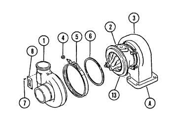
DISASSEMBLY
1. MARK COMPRESSOR HOUSING (1), BEARING
HOUSING (2), TURBINE HOUSING (3),
AND DIFFUSER (13), FOR CORRECT PART
ORIENTATION AT ASSEMBLY.
2. PLACE TURBOCHARGER IN A VISE AND
CLAMP BY THE TURBINE HOUSING INLET
FLANGE (A). PLACE SOFT METAL COVERS
OVER VISE JAWS TO PREVENT DAMAGE TO
TURBINE HOUSING (3).
3. LOOSEN NUT (4) ON V-BAND CLAMP (5).
4. REMOVE COMPRESSOR HOUSING (1),
V-BAND CLAMP (5) AND RECTANGULAR
RING SEAL (6). DISCARD RECTANGULAR
RING SEAL (6).
5. IF NECESSARY, REMOVE DATAPLATE (8).
a. Remove four drivescrews (7).
b. Remove dataplate (8).
4-16
|