| |
TM10-3930-660-34
4-3.
FUEL INJECTOR - TEST/REPLACE (Cont’d)
b. Operate pump lever at a rate that causes
nozzle to chatter softly while discharging
fuel in a broad and finely atomized pattern.
If conditions of prior note are not met,
replace nozzle.
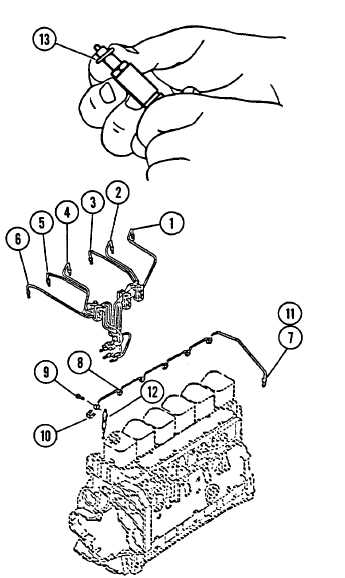
INSTALLATION
1. APPLY ANTI-SEIZE COMPOUND TO HOLD-
DOWN NUT THREADS.
2. INSTALL FUEL INJECTORS (12).
a. Install one new copper injector seal (13)
on each nozzle.
b. Install injector, (12) using care to align
button on injector nozzle holder with notch
in cylinder head bore.
c. Torque injector (12) nut to 44 lb. ft
d. Install new banjo connector seal (10) in
gap between nozzle holder and injector
nut.
e. Install fuel manifold (8) and new seals
(11), and secure to injectors with screws
(9). Tighten nuts (7) on manifold (8).
f. Loosely connect fuel high pressure tubes
(1-6) to fuel injectors. Leave connections
loose until bleeding procedure (STEP 3,
below) is completed.
3. CONNECT NEGATIVE BATTERY CABLE,
M10-3930-660-20.
4. BLEED FUEL SYSTEM.
WARNING
To bleed fuel system, engine must be
a. Briefly crank engine to allow air
placed in a run condition. Because
entrapped in high fuel pressure
engine may start during bleeding
lines to escape around fittings on
procedure, all necessary safety
fuel injectors.
precautions must be followed. See
TM10-3930-660-10 (unit operation manual).
b. Tighten fittings to 216 in. lb.
4-8
|