| |
TM 10-3930-660-34
CHAPTER 4
FUEL SYSTEM MAINTENANCE
Section I. DESCRIPTION AND DATA
4-1.
GENERAL.
Fuel system maintenance procedures not covered in this section may be found inTM 10-3930-660-20.
4-2.
PRINCIPLES OF OPERATION.
a.
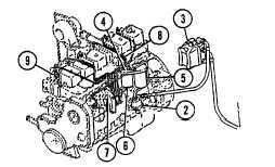
Fuel Flow. Fuel is pulled from fuel tank (1) by a cam actuated fuel transfer pump (2). The fuel is drawn through a
chassis mounted combination filter/separator (3) and into the fuel transfer pump (2) which supplies low-pressure
fuel (3-5psi) to the engine mounted fuel filter head (4). The fuel is pumped through a canister-type combination
filter/separator (5) and a canister-type filter (6) and into the fuel injection pump (7). The engine uses a distributor-
type fuel pump supplied by Robert Bosch. The distributor pump builds the high injection pressure (3,200 psi)
required for combustion, and routes the fuel through individual high-pressure fuel lines (8) to each injector (9).
When the high-pressure fuel reaches the injector, the pressure lifts a needle valve against spring tension in the
injector to let the fuel enter the combustion chamber. The fuel injector has very small holes in the tip that change
the flow of fuel to a very fine spray that burns easily in the cylinder. Leakage of fuel past the needle valve stem is
used for lubrication of the injector. This leakage enters a fuel drain manifold. The fuel drain manifold routes
controlled venting (lubrication) from the distributor injection pump and injectors back to the fuel tank.
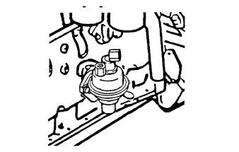
b.
Fuel Transfer Pump. The fuel transfer pump is mechanically driven by a lobe on the camshaft. The fuel transfer
pump is located on the left side of the engine.
4-1
|