| |
TM 10-3930-660-34
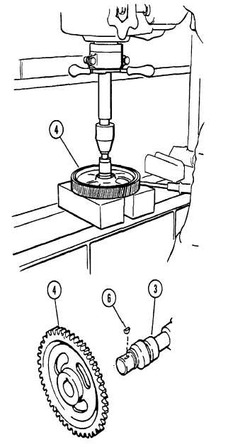
3-18. CAMSHAFT, CAMSHAFT GEAR, AND CAMSHAFT BUSHING - REPLACE (Cont’d)
DISASSEMBLY
1.
USE A PRESS TO PUSH GEAR (4) FROM
CAMSHAFT (3).
2.
REMOVE KEY (6) FROM CAMSHAFT.
3.
USE CROCUS CLOTH TO REMOVE ALL BURRS
AND SMOOTH ANY ROUGH SURFACES ON THE
CAMSHAFT THAT COULD HAVE BEEN CAUSED
BY GEAR REMOVAL.
CLEANING
See Cleaning Instructions, para. 2-10.
INSPECTION
1.
INSPECT CAMSHAFT BUSHING AND
CAMSHAFT BORES IN CYLINDER BLOCK.
a. Inspect camshaft bushing and camshaft bores
for
burrs, scoring, grooves, and pitting.
b. Measure front camshaft bushing I.D. Acceptable
range is 2.1295 to 2.1314 in.
NOTE
If intermediate and rear camshaft bores have
service bushings installed, the I.D. dimension
must be within the tolerance specified above in
step b.
c. Measure intermediate and rear camshaft bores
I.D. Acceptable bore I.D. range is 2.1295 to
2.1314 in. If bores are worn beyond this
specification, the block must be machined and
service bushings installed, or the block must be
replaced. Refer to Depot level maintenance.
NOTE
If new valve tappets are being installed, the
camshaft and camshaft bushing must be
replaced
3-113
|