| |
TM 10-3930-660-34
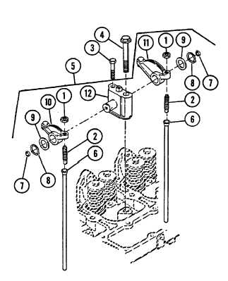
3-16.
ROCKER ARM ASSEMBLY - RIEPACE/REPAIR (Cont’d)
3.
MEASURE ROCKER ARM SUPPORT SHAFT
DIAMETER.
Minimum Allowable Diameter: 0.746 inch
ASSEMBLY
NOTE
Be sure to assemble intake rocker arm (10) and exhaust rocker
arm (11) in the correct location.
ASSEMBLE ROCKER ARM ASSEMBLY (5).
a.
Assemble adjusting screws (2) and nuts (1) to
rocker levers (10 and 11).
b.
Lubricate both ends of support shaft with engine
lubricating oil.
c.
Check to make sure adjusting screws (2) are
completely backed out.
d.
Assemble intake rocker arm (10) and exhaust
rocker arm (11) onto support (12) shaft.
e.
Install two washers (9), retaining rings (8J, and
new expansion plugs (7) if removed.
f.
Repeat STEPS a through e for the other five rocker
arm assemblies (5).
3-107
TM 10-3930-660-34
3-16.
ROCKER ARM ASSEMBLY - REPLACE/REPAIR (Cont’d)
INSTALLATION
1.
INSTALL 12 PUSH RODS (6) INTO SAME
POSITION IN ENGINE AS ORIGINALLY
PLACED. LUBRICATE PUSH ROD SOCKETS
WITH CLEAN ENGINE LUBRICATING OIL.
2.
INSTALL ROCKER ARM ASSEMBLY (5) IN
ORIGINAL POSITION. TIGHTEN
CAPSCREWS (4) TO FINAL TORQUE VALUE
IN THREE STEPS.
a.
Place rocker arm assembly (5) onto
cylinder head.
|