 |
|||
|
|
|||
|
|
|||
| ||||||||||
|
|
 TM 10-3930-660-24-2
MLRS ATTACHMENT CONTROL VALVE MAINTENANCE - CONTINUED
0304 00
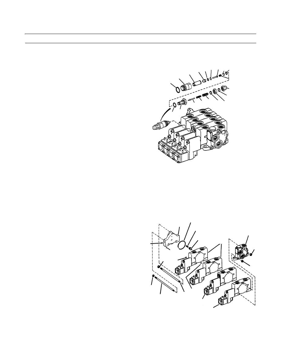
DISASSEMBLY - CONTINUED
NOTE
28 27 26 25 23
30 29
21
Do not remove relief valves unless they
25
14
are being disassembled.
15
4.
Remove plug (13) from body (21). Remove and dis-
17
card O-ring (14).
18 17 16
20 19
5.
Remove nuts (15 and 16). Remove and discard two
22 13
seals (17) from nuts (15 and 16).
6.
Remove adjusting screw (18), spring (19) and poppet
(20).
7.
Remove O-ring (22), back-up ring (23) and O-ring
(24). Discard O-rings and back-up ring.
8.
Remove spring (25), piston (26), O-ring (27), back-up
409-1380
ring (28) and poppets (29 and 30). Discard O-ring and
back-up ring.
NOTE
Mark housing sections. These marks will be used for assembly.
9.
Place valve so it is resting on housing inlet (31).
NOTE
42
Use care when removing outlet and hous-
36
45
ing sections. Do not lose poppets and
31
springs that may eject from housing sec-
46
tions.
39
37
32
10.
Remove nuts (32 and 33), tie rod (34), two tie rods
38
(35) and outlet housing (36).
32
44
11.
Remove plugs (37 and 38), if necessary.
33
12.
Separate housing (39 thru 41) and inlet housing (31).
13.
Remove and discard one large O-ring (42) and two
small O-rings (43) from each face of housing section.
33
43
34
NOTE
35
40
41
Valve section closest to outlet housing has
409-1381
no shuttle plate.
14.
Remove three shuttle plates (44), four springs (45) and
four compensator pistons (46).
0304 00-2
|
|
Privacy Statement - Press Release - Copyright Information. - Contact Us |
