 |
|||
|
|
|||
|
|
|||
| ||||||||||
|
|
 TM 10-3930-660-24-2
TANDEM GEAR PUMP MAINTENANCE - CONTINUED
0302 00
ASSEMBLY
CAUTION
Do not grip on or near any machined surfaces during disassembly or assembly. Failure to follow this precau-
tion will cause part damage.
NOTE
Wipe all sealing surfaces clean and dry. Apply film of clean hydraulic oil to all seals as they are installed.
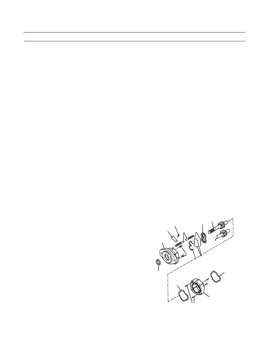
1.
Secure plate (39) with two screws (38).
NOTE
Place end cover in a vise with mounting face down.
2.
If removal of two plugs (37) was necessary, apply on threads. Install them in end cover (30). Stake each plug with a
punch at both ends of screwdriver slot and around edges. Peen edge of hole 1/32 to 1/16 in. (0.79 to 1.59 mm) with a 1-
1/2 in. (38 mm) steel diameter ball.
3.
Apply permatex aviation form-a-gasket no. 3 sealant on lip seal (36). With metal side of seal up, use an arbor press and
a bar (1-3/4 in. [44.5 mm] diameter by 2 in. [51 mm] long bar), press seal (36) into end cover (30). Press seal flush with
recess. Wipe off excess sealant.
4.
Apply grease on two new seals (31). Install new seals into grooves on gear housing (21).
CAUTION
If parts are difficult to fit during assembly, tap gently with a soft hammer. Use care to prevent part damage.
5.
Ensure that dowel pins (29) are in place. Install gear housing (21) onto end cover (30). Gently tap gear housing (21) tight
against end cover (30). Use care to prevent damage to new seals (31).
6.
Install new seals (33 thru 35) into grooves in thrust
27
32
38
plate (32) with flat side of new seal (33) facing away
39
34
4
from thrust plate.
7.
Slip thrust plate (32) through gear housing (21) into
30
28
end cover (30). The new seal (33) should face away
from end cover (30). The relief groove in thrust plate
37
(32) should face pump outlet side.
35
33
8.
Slide driven gear (28) through gear housing (21) into
31
36
end cover (30).
31
9.
Apply grease on fabricated drive gear installation tool.
Place shaft of greased drive gear (27) inside tool. Slide
both through end cover (30) with a twisting motion.
21
The integral gears should rest against thrust plate (32).
29
Remove drive gear installation tool. Apply lubricating
409-1374
oil on gears (27 and 28).
0302 00-4
|
|
Privacy Statement - Press Release - Copyright Information. - Contact Us |
