 |
|||
|
|
|||
|
|
|||
| ||||||||||
|
|
 TM 10-3930-660-24-2
BRAKE CONTROL VALVE MAINTENANCE - CONTINUED
0299 00
ASSEMBLY - CONTINUED
4.
Install new lockwasher (58) and screw (57). Torque screw (57) to 22-27 lb-ft (30-37 Nm).
5.
Install two new lockwashers (56) and two screws (55). Torque screws (55) to 22-27 lb-ft (30-37 Nm).
6.
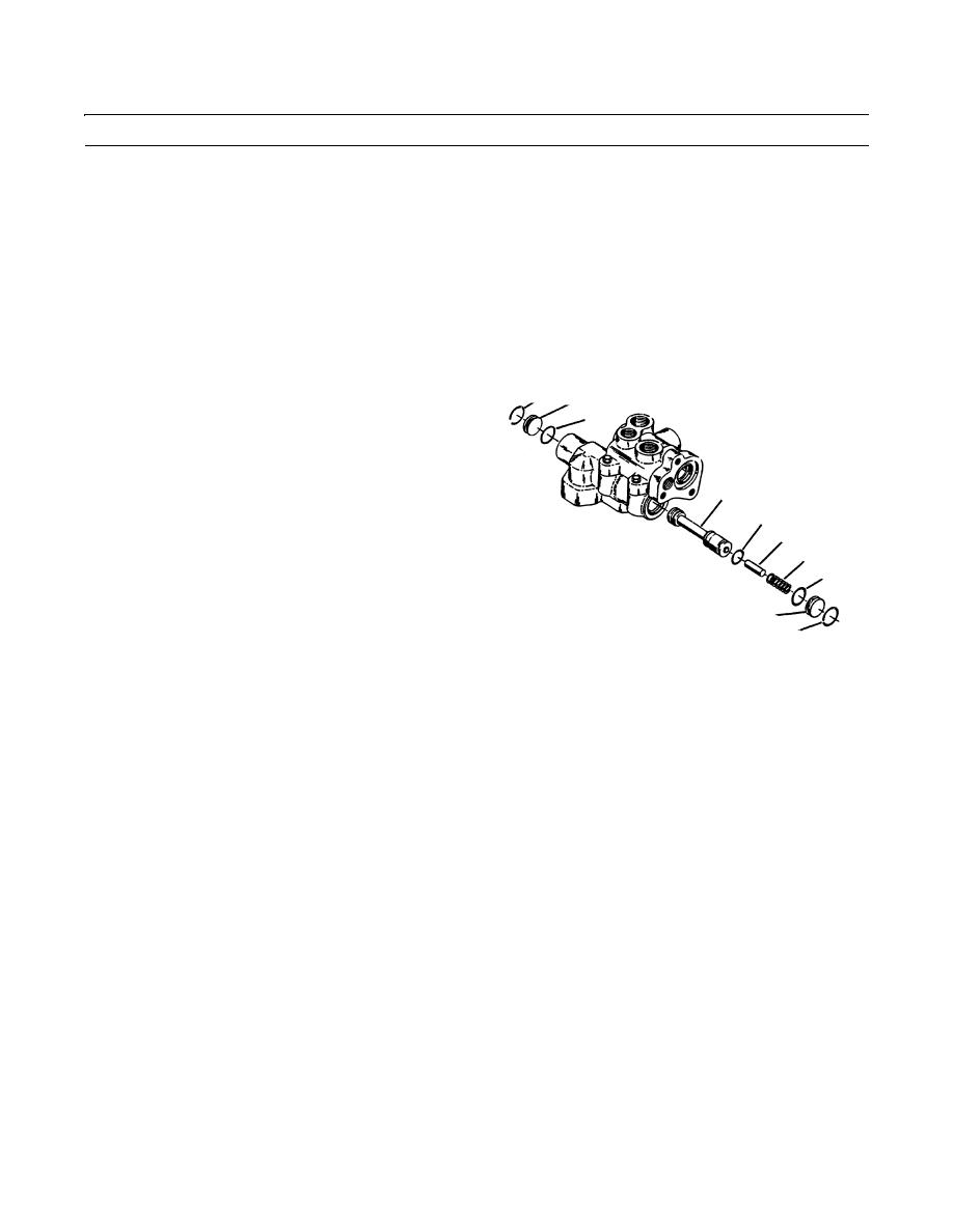
Install new O-ring (52) on plug (50). Install plug (52) with retaining ring (51).
CAUTION
Use care to prevent damage to lands on spool and inside bore. Do not force spool into valve. Failure to fol-
low this precaution will cause part damage.
7.
Install new O-ring (54) on spool (53). Insert spool (53)
51
50
into valve bore. Ensure that spool (53) is oriented cor-
52
rectly. Ensure that spool (53) makes contact with plug
(50) on opposite side of valve.
8.
Install stop (48) and spring (47).
53
9.
Install new O-ring (49) on plug (45). Install plug (45)
with retaining ring (46).
54
48
47
49
45
46
409-1332
10.
Install new filter (44), washer (43), new O-ring (42), seat (41), new poppet (40) and spring (39).
11.
Install new O-ring (38) on adjusting screw (37). Install adjusting screws (37) and torque to 15-20 lb-ft (20-27 Nm).
12.
Install nut (36) and torque to 15-20 lb-ft (20-27 Nm).
13.
Install new O-rings (34 and 35) on new insert (33). Use a wooden dowel to push new insert (33) into valve.
14.
Install spool (32) into new insert (33). Insert the short end of spool (32) first.
15.
Install ball (31). Ensure that ball (31) rests on new insert (33).
16.
Apply clean grease on end of spring (29) to hold stop (30) in place. Install stop (30) with spring (29).
17.
Install new O-ring (28) on plug (27). Install and torque plug (27) to 40-50 lb-ft (54-68 Nm).
CAUTION
Ensure that ball is on seat before proceeding. Failure to do so could cause part damage.
18.
Apply clean grease to hold ball (26) and seat (25) to spring (24). Install ball (26), seat (25) and spring (24).
NOTE
The maximum accumulator pressure is adjusted by turning plug. The high pressure limit is increased by
turning plug into valve. The low pressure limit is decreased by turning plug out from valve.
19.
Install new O-ring (23) on plug (22). Install plug (22) and turn same number of times as recorded during disassembly.
0299 00-5
|
|
Privacy Statement - Press Release - Copyright Information. - Contact Us |
