 |
|||
|
|
|||
|
|
|||
| ||||||||||
|
|
 TM 10-3930-660-24-2
FRONT DIFFERENTIAL CARRIER ASSEMBLY MAINTENANCE - CONTINUED
0296 00
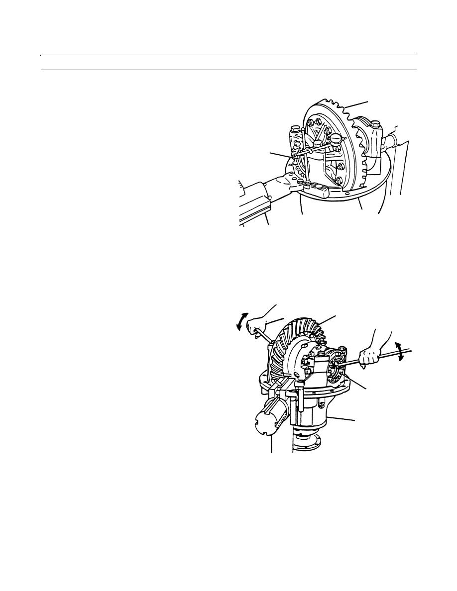
ADJUSTMENT
1.
Attach a dial indicator on the mounting flange of the
13
differential carrier (8).
2.
Adjust the dial indicator so that the plunger is against
the back surface of the ring gear (13).
4
8
409-1253
CAUTION
When turning bearing adjusting rings, always use a tool that engages two or more opposite notches in the
ring. A large screwdriver can be used for this purpose. Failure to do so could cause damage to adjusting ring
lugs.
3.
Loosen the bearing adjustment ring (4) opposite ring
13
gear (13) so that a small amount of end play shows on
dial indicator. Move differential assembly and ring
gear (13) left and right with suitable pry bars while
reading dial indicator. Do not allow pry bars to touch
bearings (9 thru 11).
4.
Tighten bearing adjustment ring (4) opposite ring gear
(13) so that no end play shows on dial indicator. Move
the differential assembly and ring gear (13) left and
right as needed.
4
5.
Tighten each bearing adjusting ring (4) one notch from
zero end play.
8
6.
To check runout of ring gear (13), attach dial indicator
on mounting flange of differential carrier (8). Adjust
dial indicator so that plunger is against back surface of
ring gear (13).
409-1254
7.
Adjust dial of indicator to zero.
0296 00-12
|
|
Privacy Statement - Press Release - Copyright Information. - Contact Us |
