 |
|||
|
|
|||
|
|
|||
| ||||||||||
|
|
 TM 10-3930-660-24-2
TORQUE CONVERTER REPAIR - CONTINUED
0288 00
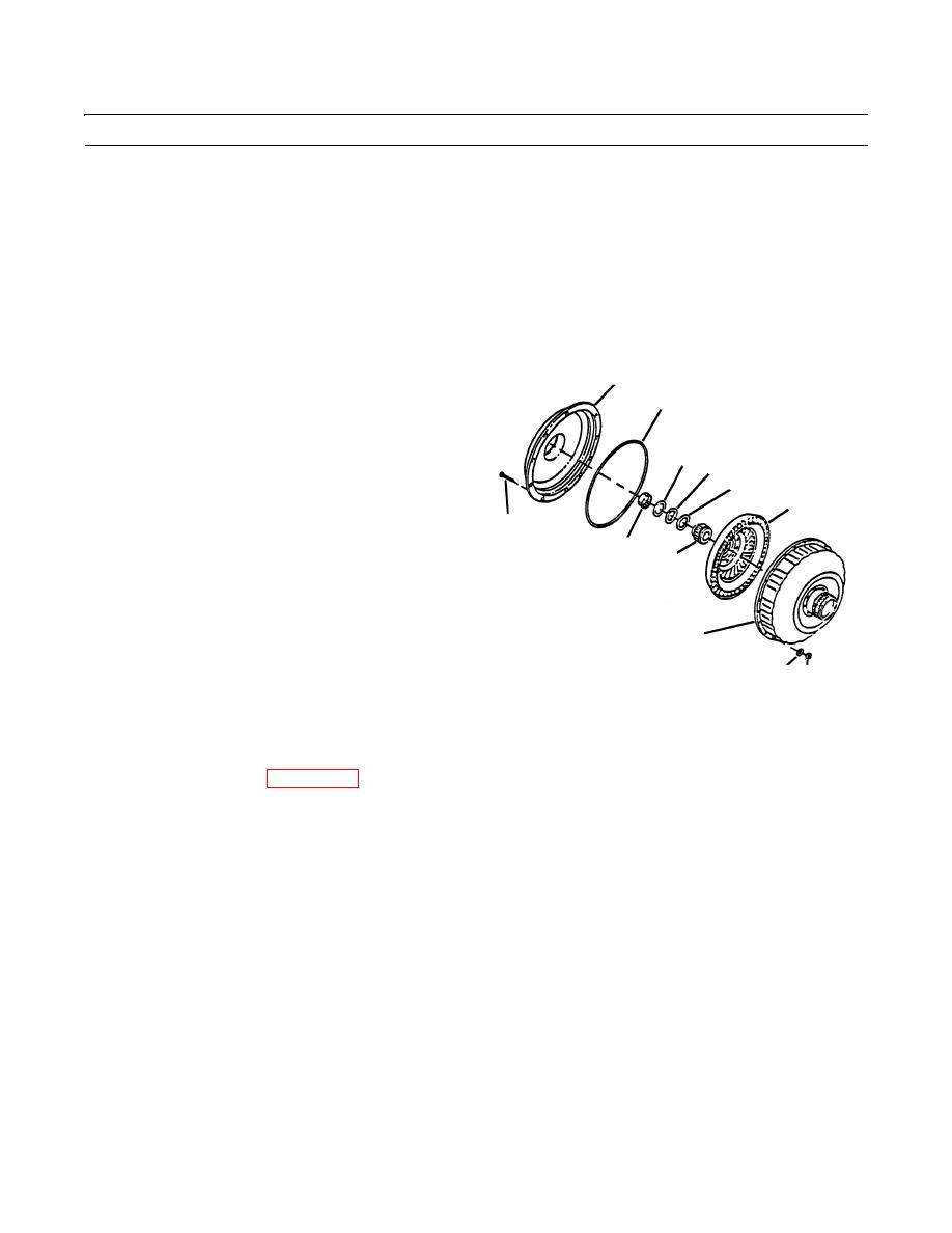
ASSEMBLY - CONTINUED
5.
Install outer race (21), sprag clutch assembly (20) and inner race (19). Clutch assembly flange should be toward front of
converter as shown. Stator will free-wheel counterclockwise viewed from output end.
6.
Install sprag clutch assembly (20) with flanged edge of cage toward side of stator (16) marked "FRONT" or the letter
"F". The stator will free-wheel counterclockwise when viewed from output side.
7.
Install two clutch retainers (18) and retaining ring (17).
8.
Install stator (16) in impeller (2) so that the word "FRONT" faces away from impeller.
9.
Install inner thrust washer (15), needle thrust bearing (14) and outer thrust washer (13).
10.
Install turbine (12) and turbine hub (11).
1
11.
Install inner thrust race (8), needle thrust bearing (7)
10
and outer thrust race (6).
12.
Install bearing (9) 0.040 in. (1.016 mm) below thrust
6
race (6) surface.
7
13.
Install new O-ring (10) on front cover (1).
8
12
14.
Align marks made at disassembly between front cover
5
(1) and impeller (2). Install front cover (1).
9
11
2
4
3 409-1139a
15.
Apply loctite to threads of capscrews (5). Install twenty capscrews, twenty flatwashers (4) and twenty hex nuts (3).
Torque capscrews to 25 lb-ft (34 Nm).
16.
Install torque converter (WP 0236 00).
17.
Operate equipment, check for proper operation and leaks (TM 10-3930-660-10).
END OF WORK PACKAGE
0288 00-3/(-4 Blank)
|
|
Privacy Statement - Press Release - Copyright Information. - Contact Us |
