 |
|||
|
|
|||
|
|
|||
| ||||||||||
|
|
 TM 10-3930-660-24-2
STARTER REPAIR (165 HP) - CONTINUED
0287 00
INSPECTION - CONTINUED
7.
Check for short circuits in armature (13) using a growler and steel strip.
8.
Rotate armature (13) in growler.
9.
Hold steel strip (e.g., hacksaw blade) across armature slots as armature rotates. Steel strip will vibrate as slot between
shorted bars passes under steel strip.
10.
If short circuit is detected, check for build up of copper dust or other conductive material between commutator bars.
Clean out copper dust and check again for short circuits. If commutator bars are shorted, replace armature (13).
11.
Check armature for grounds or open circuits.
12.
Set multimeter to ohms, on highest scale. Check for grounds by measuring resistance between commutator and one
armature bar.
13.
Switch multimeter to lowest scale.
14.
Place multimeter leads against two adjacent commutator bars and observe multimeter. Multimeter needle should swing
to zero and remain.
15.
Repeat check for all commutator bars by moving one multimeter lead at a time. There must be continuity between each
pair of bars. If there is no continuity between one or more pairs of bars, replace armature (13).
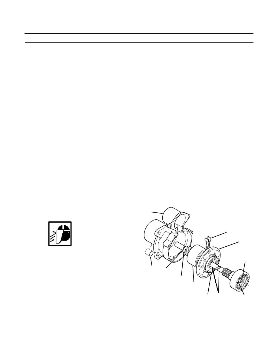
ASSEMBLY
1.
If removed, install bushing (40) in drive housing (22).
2.
Install bearing (39) on driveshaft (30).
3.
Position shaft support (31) and drive clutch assembly
22
(32) on drive shaft (30).
27
31
WARNING
Use care when removing snap and retaining
36
rings. Snap and retaining rings are under spring
tension and can act as projectiles when released
40
and could cause severe eye injury.
38
37
4.
Install pinion stop (37) and new retaining ring (38) on
32
drive shaft (30). Retaining ring may have to be forced
over driveshaft using a block of wood.
39
30
33,34,35
5.
Install plug (36) and washers (33 thru 35) on drive
409-1837 01410
TR
shaft (30).
6.
Install shifter fork (27), drive clutch assembly (32), shaft support (31), and driveshaft (30) as an assembly in drive hous-
ing (22).
0287 00-6
|
|
Privacy Statement - Press Release - Copyright Information. - Contact Us |
