 |
|||
|
|
|||
|
|
|||
| ||||||||||
|
|
 TM 10-3930-660-24-2
ALTERNATOR ASSEMBLY MAINTENANCE (165 HP) - CONTINUED
0285 00
TESTING - CONTINUED
4.
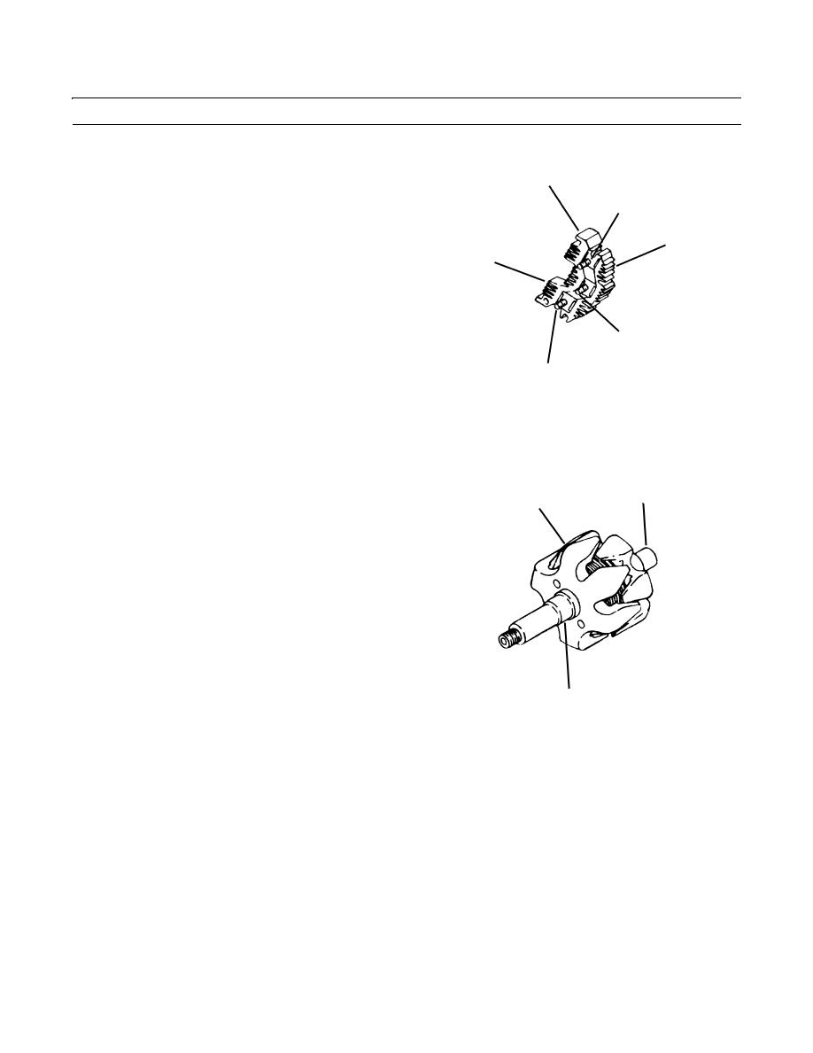
To test rectifier bridge assembly (21), connect multim-
59
eter from grounded heat sink (55) to diode terminal
56
(56) and note resistance reading.
5.
Reverse multimeter leads or reverse meter polarity
55
and again note resistance reading.
21
6.
At one polarity, resistance reading should be low and
at the other polarity, resistance reading should be very
high, if diode is good. If diode is faulty, both readings
will be either low or high.
7.
Repeat above sequence between grounded heat sink
57
(55) and diode terminals (57 and 58), and then
between insulated heat sink (59) and each diode termi-
409-1863
58
nal (56 thru 58).
TR01431
8.
If any set of readings indicates a faulty diode, replace
complete rectifier bridge (21).
9.
To test rotor assembly (9) for short of open circuits, connect multimeter between slip rings (50), in turn, and rotor shaft
(60) (connection A). Observe resistance reading on ohmmeter.
10.
Resistance reading should be high (infinite). If not,
rotor (9) is defective and must be replaced.
60
9
11.
Connect multimeter leads across slip rings (50) (con-
nection B). Observe resistance reading on ohmmeter.
A high (infinite) resistance reading indicates an open
rotor winding and rotor (9) must be replaced.
409-1864
50
TR01432
0285 00-5
|
|
Privacy Statement - Press Release - Copyright Information. - Contact Us |
