 |
|||
|
|
|||
|
|
|||
| ||||||||||
|
|
 TM 10-3930-660-24-2
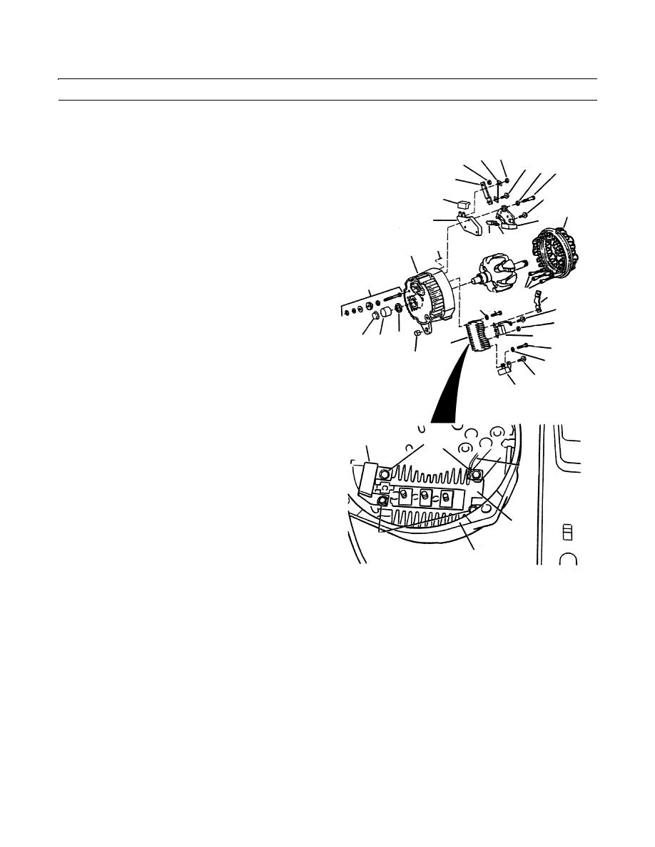
ALTERNATOR ASSEMBLY MAINTENANCE (152 HP) - CONTINUED
0284 00
DISASSEMBLY - CONTINUED
9.
Remove three nuts (16) that connect stator lead termi-
26 38
32
nal clips (17) to diode trio (18).
25 30 29
33
10.
Remove stator (8) from slip ring end frame (5).
19
11.
Remove insulated screw (19) securing diode trio (18)
27
8
to brush and holder assembly (20). Remove diode trio
28
20
(18).
20 31
43
NOTE
5
Screws and springwashers are located on
34,35,36
the rectifier bridge, closest to outside of
37
17
frame. One of the screws secures the lower
22 21
19
contact of capacitor.
16
12.
Remove two screws (21) and two springwashers (22)
18
40 39 41
from rectifier bridge (23). Discard springwashers.
23
21
42
22
NOTE
25
Screw and lockwasher assemblies are
24
located on the rectifier bridge, closest to
center of frame. One assembly secures the
upper contact of capacitor. The other
24
assembly secures wire lead.
25
13.
Remove two screw and lockwasher assemblies (25)
26
from rectifier bridge (23). Remove capacitor (24) and
rectifier bridge (23) from frame (5). Discard screw and
lockwasher assemblies.
14.
Remove rubber cover (27) from terminals of regulator
23
(28).
21,22
15.
Remove insulated screw (19), screw (29) and lock-
5
washer (30), securing brush and holder assembly (20),
brush springs (31) and regulator (28). Discard lock-
409-1098
washer. Remove parts (20, 28 and 31) from frame (5).
16.
If necessary, remove nut (32), connector (33) and battery terminal assembly parts (34).
17.
If necessary, remove relay terminal cap (35), relay terminal assembly parts (36) and connector (37).
18.
If necessary, remove nut (38) and wire lead (26) from regulator (28).
NOTE
If roller bearing is not being removed, apply pressure sensitive tape over it for protection against dirt. Do not
use friction tape or other tape that will leave a residue behind.
19.
If necessary for replacement, push roller bearing (39) out of frame (5) and remove seal (41) and plug (40). Discard seal.
20.
If necessary, remove bushing (42) and pin (43) from frame (5).
0284 00-2
|
|
Privacy Statement - Press Release - Copyright Information. - Contact Us |
