 |
|||
|
|
|||
|
|
|||
| ||||||||||
|
|
 TM 10-3930-660-24-2
BOOM ASSEMBLY REPLACEMENT - CONTINUED
0261 00
INSTALLATION - CONTINUED
8.
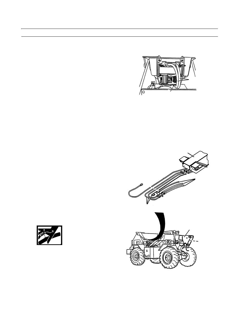
Carefully lower boom assembly (8) with hoist and sling until front of outer boom section is on jackstand or support.
9.
Secure hydraulic hoses (3) to bottom of boom assem-
bly with new locknuts (A), capscrews (B) and clamp
halves (C).
10.
Connect rod ends of boom hoist cylinder (12) to boom
assembly (8).
3
11.
Reposition slings to front of outer boom section.
12.
Lift boom assembly (8) until cylinder pivot pin holes
of boom assembly (8) are just above cab.
A,B,C
409-1400
13.
Lift boom hoist cylinders (12) into position and sup-
port cylinders.
CAUTION
Use hoist and sling to make final alignment with cylinder rod eye and pivot pin hole. Do not use the joystick
to make final alignment; damage to rod eye bushing could result.
NOTE
One boom hoist cylinder will begin to extend before the other. Install this cylinder first. Second cylinder will
begin to extend after first cylinder is connected.
14.
Start engine (TM 10-3930-660-10).
15.
Use joystick to extend boom hoist cylinder (12) until
8
cylinder rod eye is aligned with pivot pin hole of
boom assembly (8). Stop engine (TM 10-3930-660-
10).
NOTE
Apply antiseize compound to pivot pin as installed.
9
16.
Secure pivot pin (13) to boom assembly (8) with cap-
screw (14) and new locknut (15).
17.
Repeat steps 14 thru 16 for other boom hoist cylinder
(12).
18.
Connect three hoses (9) to lines (10) at underside of
boom assembly (8).
10
19.
Start engine and raise boom assembly (8) as required
to access lines (10). Stop engine (TM 10-3930-660-
10).
8
11
WARNING
Remove hose caps carefully prior to con-
necting hoses in step 20. Hydraulic oil
may be under pressure.
20.
Connect three hoses (9) to three lines (10) at underside
409-1301
of boom assembly (8).
21.
Start engine and lower boom assembly (8) until hori-
zontal. Stop engine (TM 10-3930-660-10).
0261 00-9
|
|
Privacy Statement - Press Release - Copyright Information. - Contact Us |
