 |
|||
|
|
|||
|
|
|||
| ||||||||||
|
|
 TM 10-3930-660-24-2
CARRIAGE ASSEMBLY REPLACEMENT - CONTINUED
0260 00
INSTALLATION - CONTINUED
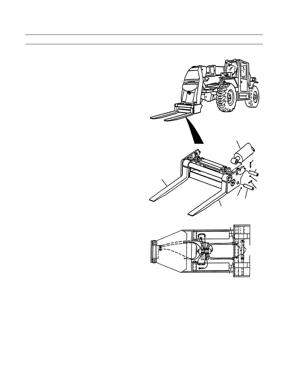
4.
Install carriage pivot pins (6).
5.
Operate hoist as necessary to align mounting holes in
carriage and MLRS frame.
NOTE
Apply antiseize compound on pins as installed.
6.
Install two carriage pivot pins (6), two capscrews (7)
and two new locknuts (8).
7.
Connect four hydraulic lines (1) to fork sideshift cyl-
inders.
2
8.
Start engine (TM 10-3930-660-10).
9.
Extend carriage tilt cylinders (1) to align pivot pin
holes in carriage frame and in cylinder rod ends.
3
NOTE
5
Apply anti-seize compound on pins.
9
10.
Install two carriage tilt cylinder pivot pins (5), two
4
capscrews (3) and two new locknuts (4).
7
11.
Shut off engine (TM 10-3930-660-10).
8
6
9
12.
Disconnect hoist and remove lifting sling from car-
409-1395
riage frame.
13.
Install fork auto leveler switch (WP 0080 00).
1
14.
Install backrest (WP 0160 00).
15.
Lubricate carriage tilt cylinder pivot pins (4) and car-
riage pivot pins (5).
1
16.
Start engine (TM 10-3930-660-10).
17.
Operate fork sideshift function several times in each
direction to bleed fork sideshift lines of air.
1
409-1394
18.
Shut off engine (TM 10-3930-660-10).
END OF WORK PACKAGE
0260 00-4
|
|
Privacy Statement - Press Release - Copyright Information. - Contact Us |
